ファイル:Navier Stokes Laminar.svg

元のファイル(SVG ファイル、900 × 720 ピクセル、ファイルサイズ: 9.37メガバイト)

概要

解説
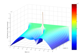
English: SVG illustration of the classic Navier-Stokes obstructed duct problem, which is stated as follows. There is air flowing in the 2-dimensional rectangular duct. In the middle of the duct, there is a point obstructing the flow. We may leverage Navier-Stokes equation to simulate the air velocity at each point within the duct. This plot gives the air velocity component of the direction along the duct. One may refer to [1], in which Eq. (3) is a little simplified version compared with ours.
日付
原典

投稿者自身による著作物

Brief description of the numerical method

The following code leverages some numerical methods to simulate the solution of the 2-dimensional Navier-Stokes equation.

We choose the simplified incompressible flow Navier-Stokes Equation as follows:

The iterations here are based on the velocity change rate, which is given by

Or in X coordinates:

The above equation gives the code. The case of Y is similar.
作者 IkamusumeFan
その他のバージョン
SVG 開発
InfoField
 
このSVGのソースコードは正しい
 
この ベクター画像Matplotlibで作成されました。
ソースコード
InfoField

Python code

from __future__ import division from numpy import arange, meshgrid, sqrt, zeros, sum import matplotlib.pyplot as plt from mpl_toolkits.mplot3d import Axes3D from matplotlib.ticker import ScalarFormatter from matplotlib import rcParams   rcParams['font.family'] = 'serif' rcParams['font.size'] = 16   # the layout of the duct laminar x_max = 5 # duct length y_max = 1 # duct width  # draw the frames, including the angles and labels ax = Axes3D(plt.figure(figsize=(10, 8)), azim=20, elev=20) ax.set_xlabel(r"$x$", fontsize=20) ax.set_ylabel(r"$y$", fontsize=20) ax.zaxis.set_rotate_label(False) ax.set_zlabel(r"$v_x$", fontsize=20, rotation='horizontal') formatter = ScalarFormatter(useMathText=True) formatter = ScalarFormatter() formatter.set_scientific(True) formatter.set_powerlimits((-2,2)) ax.w_zaxis.set_major_formatter(formatter) ax.set_xlim([0, x_max]) ax.set_ylim([0, y_max])  # initial speed of the air ini_v = 3e-3 mu = 1e-5 rho = 1.3  # the acceptable difference when termination accept_diff = 1e-5 # time interval time_delta = 1.0 # coordinate interval delta = 1e-2; X = arange(0, x_max + delta, delta) Y = arange(0, y_max + delta, delta) # number of coordinate points x_size = len(X) - 1 y_size = len(Y) - 1 Vx = zeros((len(X), len(Y))) Vy = zeros((len(X), len(Y))) new_Vx = zeros((len(X), len(Y))) new_Vy = zeros((len(X), len(Y)))  # initial conditions Vx[1: x_size - 1, 2:y_size - 1] = ini_v   # start evolution and computation res = 1 + accept_diff rounds = 0 alpha = mu/(rho * delta**2) while (res>accept_diff and rounds<100):     """     The iterations here are based on the velocity change rate, which     is given by          \frac{\partial v}{\partial t} = \alpha\nabla^2 v - v \cdot \nabla v          with \alpha = \mu/\rho.     """     new_Vx[2:-2, 2:-2] = Vx[2:-2, 2:-2] +  time_delta*(alpha*(Vx[3:-1, 2:-2] +         Vx[2:-2, 3:-1] - 4*Vx[2:-2, 2:-2] + Vx[2:-2, 1:-3] + Vx[1:-3, 2:-2]) -         0.5/delta * (Vx[2:-2, 2:-2] * (Vx[3:-1, 2:-2] - Vx[1:-3, 2:-2]) +         Vy[2:-2, 2:-2]*(Vx[2:-2, 3:-1] - Vx[2:-2, 1:-3])))      new_Vy[2:-2, 2:-2] = Vy[2:-2, 2:-2] + time_delta*(alpha*(Vy[3:-1, 2:-2] +         Vy[2:-2, 3:-1] - 4*Vy[2:-2, 2:-2] + Vy[2:-2, 1:-3] + Vy[1:-3, 2:-2]) -         0.5/delta * (Vy[2:-2, 2:-2] * (Vy[2:-2, 3:-1] - Vy[2:-2, 3:-1]) +         Vx[2:-2, 2:-2]*(Vy[3:-1, 2:-2] - Vy[1:-3, 2:-2])))              rounds = rounds + 1          # copy the new values     Vx[2:-2, 2:-2] = new_Vx[2:-2, 2:-2]     Vy[2:-2, 2:-2] = new_Vy[2:-2, 2:-2]       # set free boundary conditions: dv_x/dx = dv_y/dx = 0.     Vx[-1, 1:-1] = Vx[-3, 1:-1]     Vx[-2, 1:-1] = Vx[-3, 1:-1]     Vy[-1, 1:-1] = Vy[-3, 1:-1]     Vy[-2, 1:-1] = Vy[-3, 1:-1]      # there exists a still object in the plane     Vx[x_size//3:x_size//1.5, y_size//2.0] = 0     Vy[x_size//3:x_size//1.5, y_size//2.0] = 0      # calculate the residual of Vx     res = (Vx[3:-1, 2:-2] + Vx[2:-2, 3:-1] -            Vx[1:-3, 2:-2] - Vx[2:-2, 1:-3])**2     res = sum(res)/(4 * delta**2 * x_size * y_size)  # prepare the plot data Z = sqrt(Vx**2)  # refine the region boundary Z[0, 1:-2] = Z[1, 1:-2] Z[-2, 1:-2] = Z[-3, 1:-2] Z[-1, 1:-2] = Z[-3, 1:-2]  Y, X = meshgrid(Y, X); ax.plot_surface(X, Y, Z, rstride=1, cstride=1, cmap="summer", lw=0.1,                 edgecolors="k") plt.savefig("Navier_Stokes_Laminar.svg") 

ライセンス

この作品の著作権者である私は、この作品を以下のライセンスで提供します。
w:ja:クリエイティブ・コモンズ
表示 継承
このファイルはクリエイティブ・コモンズ 表示-継承 4.0 国際ライセンスのもとに利用を許諾されています。
あなたは以下の条件に従う場合に限り、自由に
  • 共有 – 本作品を複製、頒布、展示、実演できます。
  • 再構成 – 二次的著作物を作成できます。
あなたの従うべき条件は以下の通りです。
  • 表示 – あなたは適切なクレジットを表示し、ライセンスへのリンクを提供し、変更があったらその旨を示さなければなりません。これらは合理的であればどのような方法で行っても構いませんが、許諾者があなたやあなたの利用行為を支持していると示唆するような方法は除きます。
  • 継承 – もしあなたがこの作品をリミックスしたり、改変したり、加工した場合には、あなたはあなたの貢献部分を元の作品とこれと同一または互換性があるライセンスの下に頒布しなければなりません。
  1. Fan, Chien, and Bei-Tse Chao. "Unsteady, laminar, incompressible flow through rectangular ducts." Zeitschrift für angewandte Mathematik und Physik ZAMP 16, no. 3 (1965): 351-360.

キャプション

このファイルの内容を1行で記述してください
project

このファイルに描写されている項目

題材

ファイルの履歴

過去の版のファイルを表示するには、その版の日時をクリックしてください。

日付と時刻サムネイル寸法利用者コメント
現在の版2016年3月15日 (火) 01:062016年3月15日 (火) 01:06時点における版のサムネイル900 × 720 (9.37メガバイト)NicoguaroSmaller version
2016年3月15日 (火) 00:582016年3月15日 (火) 00:58時点における版のサムネイル900 × 720 (11.08メガバイト)NicoguaroChange the jet colormap, since it is recognized as a bad option, in general. Formatting, and pythonic code (and vectorized operations).
2014年11月6日 (木) 23:342014年11月6日 (木) 23:34時点における版のサムネイル720 × 540 (14.23メガバイト)IkamusumeFanUser created page with UploadWizard

グローバルなファイル使用状況

以下に挙げる他のウィキがこの画像を使っています:

このファイルのグローバル使用状況を表示する。

メタデータ